BIM modeling: Focus on the levels of detail (LOD) of networks and terminals

Why model networks and terminals in 3D?

The 3D modeling of networks and technical terminals has become a common practice for many people (architects, design offices, project managers, etc.), whether for one-off study projects or to have better management of this equipment over time.
By modeling this equipment, the people collaborating around a digital model will have an overall vision of them and their role in the distribution of utilities (water, electricity, gas, etc.) within a building, and therefore ultimately a better understanding of their functioning.
This modeling is generally carried out in conjunction with the architectural modeling of buildings. However, it can also be carried out independently of other batches for specific studies.
Modeling networks and terminals can have several uses such as:
- Optimizing design and installation: modeling existing networks and terminals prior to a new layout will optimize the design and installation of new equipment. Possible conflicts can be detected during the design (e.g. a water pipe that passes where an aeration duct should be installed).
- Maintenance plan: in fact, having an overview of the various networks and terminals and their characteristics (e.g. date of the last maintenance) will make it possible to plan interventions more precisely and to anticipate possible breakdowns.
- Conduct technical business simulations (e.g.: simulate flows and calculate the characteristics of fluid flow), to test different network configurations and determine which ones work best under specific conditions.
In conclusion, modeling networks and terminals is an important practice in many fields. However, for the modeling to be well aligned with the needs of the users of the model, it will be necessary to define the level of detail (LOD, for Level Of Details) of network objects and terminals.
While we were addressing the subject of LODs, mainly focused on architectural, structural, and industrial equipment modeling in This article, we wanted to complete our point here by focusing on the modeling of networks and terminals.
And if you want to deepen this concept, we can only recommend our Practical Guide: “Differentiating levels of detail (LOD): illustrations and explanations”.
Network modeling
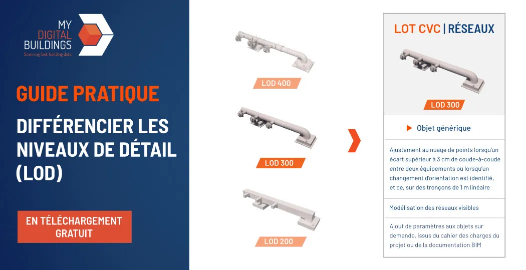
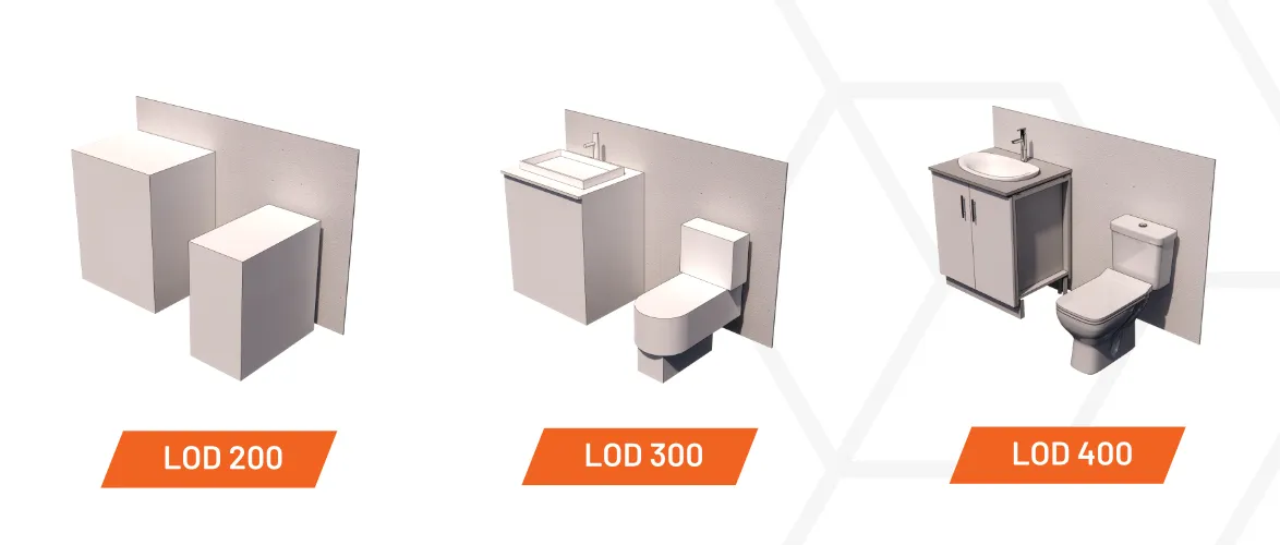
When modeling involves representing networks (Electricity, HVAC, Plumbing or SSI), they are mostly represented at LOD 200 or LOD 300, and rarely at LOD 400.
In “scan to BIM” modeling, the differences between these LODs are mainly due to the adjustment of the network modeling in relation to the point cloud, to remain more or less faithful to this imprint of reality.
3D network modeling at LOD 200
At LOD 200, only the simple volume footprint of the installations will be represented, with a straight neck-to-neck alignment between two devices: by taking a single, straight section from the beginning to the end of the network.
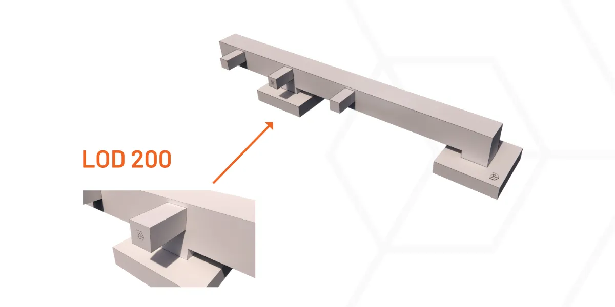
Fine and very similar networks can also be grouped in a single BIM object, as long as it makes it possible to represent the global volume of these networks.
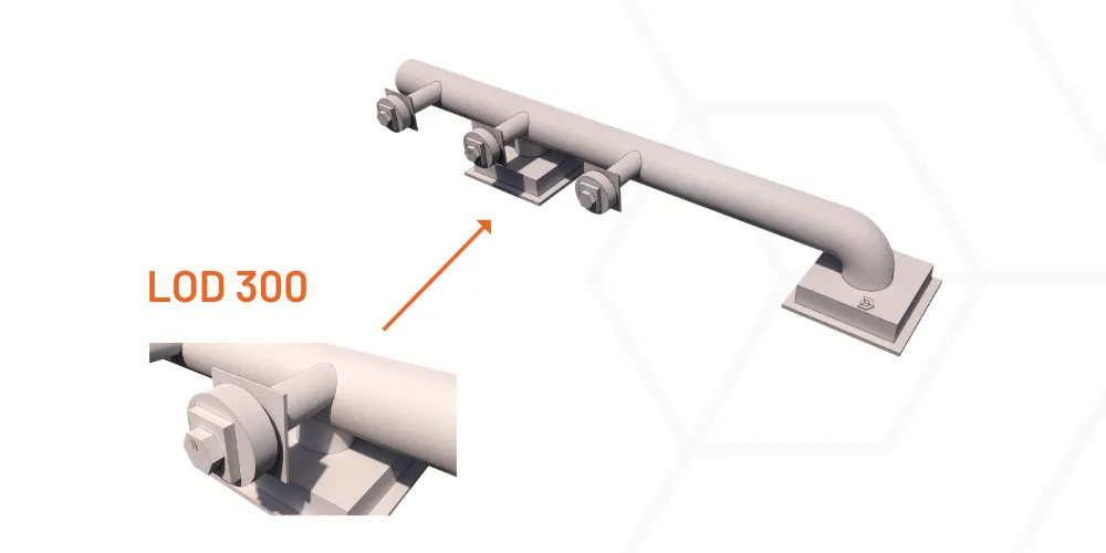
3D modeling of networks at LOD 300
At LOD 300, if there is a difference greater than 3 cm from neck to neck between two devices or when a change of orientation is identified, the 3D model is readjusted according to reality. To do this, we generally reason on sections of 1 linear meter.
3D modeling of networks with LOD 400
At LOD 400: the same logic for adjusting the orientation of the networks as at LOD 300 will be applied, reasoning with even shorter sections. At the same time, the various layers (e.g. insulation) will be specified if technical information is available to identify them.
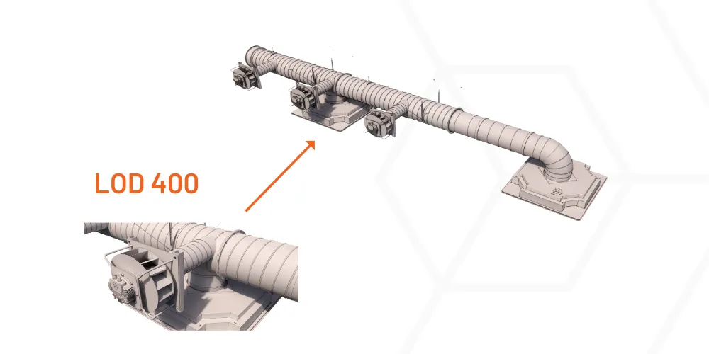
Note that at LOD 500 (or even as early as LOD 400), supplier objects will be used, while at LOD 200 and LOD 300, generic REVIT objects are used in the modeling phase.
Terminal modeling
With regard to the modeling of the terminals, they will be modeled by applying the following rules:
- At LOD 200, they will be represented by a simple volume shape.
- At LOD 300, the size, position and orientation of the terminals must be precise, and all visible elements modeled.
- At LOD 400, supplier objects will be used.
What level of detail for what use?
Common uses of LOD 200
The LOD 200 is suitable for uses requiring only an approximate representation of volumes. We recommend using the LOD 200 for networks and terminals when the users of the model only need to simulate simple layouts or to visualize the passage of networks in a building.
Common uses of LOD 300
The LOD 300 makes it possible to benefit from reliable data concerning the size, position, shape and orientation of objects, it will therefore allow more detailed studies to be carried out. Thus, flow simulations, or complex layout simulations can be sent based on objects to the LOD 300.
At the same time, if informative data is associated with the objects (e.g.: date of last maintenance, equipment technical sheet, etc.), this level of detail will also be recommended for some of the uses of Operation Maintenance Management.
Common uses of LOD 400
The LOD 400 offers an extremely precise reference of the building and its elements. Thus, it is a fairly fine level of detail to study an environment and design complex parts to be integrated as part of the work.
For example, in the context of custom design and lighting, it may be appropriate to rely on an LOD 400 modeling of cable trays and the structure to which the luminaires will be attached.
Finally, some uses in GEM very focused on networks and terminals to require LOD 400 modeling.
In any case, even if some uses are common for each LOD, these recommendations remain indicative. For each project, it will be a question of clearly identifying the BIM objectives and uses, to define the levels of detail of the objects.
Do you have a project in mind? Discover our BIM modeling services !
Let's study your project together
Contact us, we will study your project to provide you with an estimate as soon as possible
Contact us


To make sure you don't miss out on our news, subscribe to our newsletter now!
Receive quarterly updates directly in your inbox to stay informed about the latest news and events at My Digital Buildings.


